 |
Electronic Components Datasheet Search |
|
|
Electronic Components Datasheet Search |
|
The question interval is too short.
Please try again in a few seconds.

Hello, Please ask a question about M24C02-RBN6T/G Datasheet
# Example questions:
➢ Describe the function of the write control (wc) pin and explain how it contributes to data protection.
➢ What happens during a power-on reset (por) and why is it implemented?
➢ What is the purpose of the chip enable (e0, e1, e2) pins, and how are they used to select a specific device on the i2c bus?
| Part No. | M24C02-RBN6T/G |
| Manufacturer | STMICROELECTRONICS |
| Size | 208 Kbytes |
| Pages | 29 pages |
| Description | 16Kbit, 8Kbit, 4Kbit, 2Kbit and 1Kbit Serial I2C Bus EEPROM |







Device Overview:
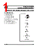
️· These are I²C-compatible Electrically Erasable Programmable Read-Only Memory (EEPROM) devices.
️· They come in various sizes: 2048/1024/512/256/128 bytes (M24C16, M24C08, M24C04, M24C02, M24C01 respectively).
️· Organized as 8-bit bytes.
I²C Communication:
️· Uses a two-wire serial interface (SCL – Serial Clock, SDA – Serial Data).
️· Slave device in the I²C protocol.
️· Device Type Identifier Code: 1010
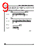
️· Data transfer is initiated with a Start condition.
️· Acknowledgment (ACK) and No Acknowledgment (NoACK) are used for data transfer control.
Key Signals/Pins:
️· SCL (Serial Clock): Strobe signal for data in/out. May require a pull-up resistor.
️· SDA (Serial Data): Bidirectional data line; requires pull-up resistor.
️· E0, E1, E2 (Chip Enable): Used with external connections to set the Device Select Code.
️· WC (Write Control): High disables writing, protects memory. If unconnected, allows writes.
Device Selection:
️· The Chip Enable pins (E0, E1, E2) are compared to external connections to define the Device Select Code. This is how the bus master selects which EEPROM on the bus to communicate with.
Important Features:
️· Power-On Reset (POR): Prevents data corruption during power-up.
️· Write Protection: The WC pin and POR circuit offer data protection.
Where the Document Is Heading:
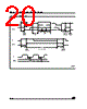
The document continues to describe the I²C bus protocol in detail, the timing diagrams, device selection and how to properly connect this EEPROM to an I²C bus.
In essence, this excerpt sets the stage for understanding how to interface with these EEPROM chips using the standard I²C communication protocol.
Device Overview:
️· These are I²C-compatible Electrically Erasable Programmable Read-Only Memory (EEPROM) devices.
️· They come in various sizes: 2048/1024/512/256/128 bytes (M24C16, M24C08, M24C04, M24C02, M24C01 respectively).
️· Organized as 8-bit bytes.
I²C Communication:
️· Uses a two-wire serial interface (SCL – Serial Clock, SDA – Serial Data).
️· Slave device in the I²C protocol.
️· Device Type Identifier Code: 1010
️· Data transfer is initiated with a Start condition.
️· Acknowledgment (ACK) and No Acknowledgment (NoACK) are used for data transfer control.
Key Signals/Pins:
️· SCL (Serial Clock): Strobe signal for data in/out. May require a pull-up resistor.
️· SDA (Serial Data): Bidirectional data line; requires pull-up resistor.
️· E0, E1, E2 (Chip Enable): Used with external connections to set the Device Select Code.
️· WC (Write Control): High disables writing, protects memory. If unconnected, allows writes.
Device Selection:
️· The Chip Enable pins (E0, E1, E2) are compared to external connections to define the Device Select Code. This is how the bus master selects which EEPROM on the bus to communicate with.
Important Features:
️· Power-On Reset (POR): Prevents data corruption during power-up.
️· Write Protection: The WC pin and POR circuit offer data protection.
Where the Document Is Heading:
The document continues to describe the I²C bus protocol in detail, the timing diagrams, device selection and how to properly connect this EEPROM to an I²C bus.
In essence, this excerpt sets the stage for understanding how to interface with these EEPROM chips using the standard I²C communication protocol.
| Part No. | M24C02-RBN6T/G |
| Manufacturer | STMICROELECTRONICS |
| Size | 208 Kbytes |
| Pages | 29 pages |
| Description | 16Kbit, 8Kbit, 4Kbit, 2Kbit and 1Kbit Serial I2C Bus EEPROM |
| Does ALLDATASHEET help your business so far? [ DONATE ] |
About Alldatasheet | Advertisement | Contact us | Privacy Policy | Link to Datasheet | Link Exchange | Manufacturer List All Rights Reserved©Alldatasheet.com |
| Russian : Alldatasheetru.com | Korean : Alldatasheet.co.kr | Spanish : Alldatasheet.es | French : Alldatasheet.fr | Italian : Alldatasheetit.com Portuguese : Alldatasheetpt.com | Polish : Alldatasheet.pl | Vietnamese : Alldatasheet.vn Indian : Alldatasheet.in | Mexican : Alldatasheet.com.mx | British : Alldatasheet.co.uk | New Zealand : Alldatasheet.co.nz |
|
Family Site : ic2ic.com |
icmetro.com |
 English ▼
  Chinese
 German
 Japanese
 Russian
 Korean
 Spanish
 French
 Italian
 Portuguese
 Polish
 Vietnamese
 Indian
 Mexican
 British
 New Zealand