 |
Electronic Components Datasheet Search |
|
|
Electronic Components Datasheet Search |
|
The question interval is too short.
Please try again in a few seconds.

Hello, Please ask a question about FP1005R3-R22-R Datasheet
# Example questions:
➢ What does the 'k-factor' represent in the context of core loss calculations, and how is it used in the formula provided?
➢ What is the impact of increasing the percentage of isat1 on the inductance characteristics?
➢ What are the key differences in the recommended peak package body temperature (tp) and time at liquidous (tl) between standard snpb solder and lead-free solder reflow profiles?
| Part No. | FP1005R3-R22-R |
| Manufacturer | EATON |
| Size | 526 Kbytes |
| Pages | 5 pages |
| Description | High frequency, high current power inductors |



1. Product Overview:
️· Product: FP1005R Series Inductor
️· Type: Shielded Power Inductor
️· Applications: DC-DC conversion, power management in a wide range of electronics (servers, computers, telecom equipment, etc.)
️· RoHS Compliant: Yes
2. Key Features and Specifications:
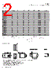
️· Size: 1005 (1.0mm x 2.5mm x 2.5mm)
️· Inductance Range: 0.8µH to 22µH (Various versions: R3, R4 have different inductance options – see the full table in the datasheet)
️· Rated Current (Irms): Varies based on inductance value (typically up to 8 Amps - check the specifics for each inductance) – derating is required for AC currents
️· Saturation Current (Isat): Varies by inductance (typically around 8-12 Amps; check datasheet).
️· Operating Temperature: -40°C to +125°C (Important: Ensure temperature rise does not exceed 125°C under worst-case conditions).
️· Packaging: Tape and reel, 950 parts per 13" reel.
3. Electrical Characteristics (Important Values):
️· OCL (Open Circuit Inductance): Tested at 100kHz, 0.1Vrms, 0.0Adc, +25°C.
️· FLL (Full Load Inductance): Tested at 100kHz, 0.1Vrms, Isat1, +25°C.
️· K-Factor: Used in calculations of core loss.
4. Part Numbering and Versions:
️· FP1005Rx: Basic part number structure. 'x' is the version indicator. Different versions (R3, R4) have slightly different electrical characteristics.
️· -Rxx: Indicates the inductance value in microhenries (µH), where 'R' is the decimal point.
5. Dimensions & Tolerances:
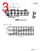
️· 1.0mm x 0.9mm x 2.5mm.
️· All dimensions are nominal. Tolerances are ±0.25mm unless otherwise specified.
6. Soldering & Reflow Profile:
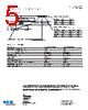
️· The datasheet provides standard SnPb and Lead-Free solder reflow profiles. Adherence to these profiles is critical for proper soldering. Pay attention to temperature and time parameters.
️· The reflow profile ensures proper solder joint formation without damaging the component.
7. Important Considerations & Warnings:
️· Temperature Rise: PCB layout, trace width, airflow, and proximity of other components significantly impact temperature rise.
️· Derating: AC currents require derating of the rated current.
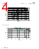
️· Core Loss: Core loss increases with peak-to-peak ripple current and frequency. The K-factor is essential for calculating Bp-p for core loss.
️· Life Support Policy: The product is not intended for use in life support systems without Eaton's written approval.
8. Core Loss vs. Bp-p and Inductance Characteristics:
️· The datasheet includes graphs that visually display the relationship between core loss, peak flux density (Bp-p), and inductance. It also displays %OCL vs %ISAT.
To effectively use this information:
️· Consult the complete datasheet: This summary provides key information, but the full datasheet contains detailed specifications, graphs, and guidelines.
️· Verify Part Number: Double-check the correct part number for your specific requirements (inductance value, version, etc.).
️· Consider Application Requirements: Factor in operating conditions (temperature, current, frequency) to ensure proper selection and performance.
1. Product Overview:
️· Product: FP1005R Series Inductor
️· Type: Shielded Power Inductor
️· Applications: DC-DC conversion, power management in a wide range of electronics (servers, computers, telecom equipment, etc.)
️· RoHS Compliant: Yes
2. Key Features and Specifications:
️· Size: 1005 (1.0mm x 2.5mm x 2.5mm)
️· Inductance Range: 0.8µH to 22µH (Various versions: R3, R4 have different inductance options – see the full table in the datasheet)
️· Rated Current (Irms): Varies based on inductance value (typically up to 8 Amps - check the specifics for each inductance) – derating is required for AC currents
️· Saturation Current (Isat): Varies by inductance (typically around 8-12 Amps; check datasheet).
️· Operating Temperature: -40°C to +125°C (Important: Ensure temperature rise does not exceed 125°C under worst-case conditions).
️· Packaging: Tape and reel, 950 parts per 13" reel.
3. Electrical Characteristics (Important Values):
️· OCL (Open Circuit Inductance): Tested at 100kHz, 0.1Vrms, 0.0Adc, +25°C.
️· FLL (Full Load Inductance): Tested at 100kHz, 0.1Vrms, Isat1, +25°C.
️· K-Factor: Used in calculations of core loss.
4. Part Numbering and Versions:
️· FP1005Rx: Basic part number structure. 'x' is the version indicator. Different versions (R3, R4) have slightly different electrical characteristics.
️· -Rxx: Indicates the inductance value in microhenries (µH), where 'R' is the decimal point.
5. Dimensions & Tolerances:
️· 1.0mm x 0.9mm x 2.5mm.
️· All dimensions are nominal. Tolerances are ±0.25mm unless otherwise specified.
6. Soldering & Reflow Profile:
️· The datasheet provides standard SnPb and Lead-Free solder reflow profiles. Adherence to these profiles is critical for proper soldering. Pay attention to temperature and time parameters.
️· The reflow profile ensures proper solder joint formation without damaging the component.
7. Important Considerations & Warnings:
️· Temperature Rise: PCB layout, trace width, airflow, and proximity of other components significantly impact temperature rise.
️· Derating: AC currents require derating of the rated current.
️· Core Loss: Core loss increases with peak-to-peak ripple current and frequency. The K-factor is essential for calculating Bp-p for core loss.
️· Life Support Policy: The product is not intended for use in life support systems without Eaton's written approval.
8. Core Loss vs. Bp-p and Inductance Characteristics:
️· The datasheet includes graphs that visually display the relationship between core loss, peak flux density (Bp-p), and inductance. It also displays %OCL vs %ISAT.
To effectively use this information:
️· Consult the complete datasheet: This summary provides key information, but the full datasheet contains detailed specifications, graphs, and guidelines.
️· Verify Part Number: Double-check the correct part number for your specific requirements (inductance value, version, etc.).
️· Consider Application Requirements: Factor in operating conditions (temperature, current, frequency) to ensure proper selection and performance.
| Part No. | FP1005R3-R22-R |
| Manufacturer | EATON |
| Size | 526 Kbytes |
| Pages | 5 pages |
| Description | High frequency, high current power inductors |
| Does ALLDATASHEET help your business so far? [ DONATE ] |
About Alldatasheet | Advertisement | Contact us | Privacy Policy | Link to Datasheet | Link Exchange | Manufacturer List All Rights Reserved©Alldatasheet.com |
| Russian : Alldatasheetru.com | Korean : Alldatasheet.co.kr | Spanish : Alldatasheet.es | French : Alldatasheet.fr | Italian : Alldatasheetit.com Portuguese : Alldatasheetpt.com | Polish : Alldatasheet.pl | Vietnamese : Alldatasheet.vn Indian : Alldatasheet.in | Mexican : Alldatasheet.com.mx | British : Alldatasheet.co.uk | New Zealand : Alldatasheet.co.nz |
|
Family Site : ic2ic.com |
icmetro.com |
 English ▼
  Chinese
 German
 Japanese
 Russian
 Korean
 Spanish
 French
 Italian
 Portuguese
 Polish
 Vietnamese
 Indian
 Mexican
 British
 New Zealand